| Arcade Optics - Optical Controls | ||
| 09/11/2009 - by Travis | ||
Everything you always wanted to know about optical arcade controls...but were afraid to askHistory/Reason for this DocumentThis document came to be because I was repairing an Arkanoid 2 (Revenge of Doh) arcade cabinet that had spinner problems. Rather than blindly replacing components because I had no idea how it worked, I decided to figure out how it worked. In doing so, I found that they are incredibly simple. In addition, I found that most optical encoder boards for arcade use are actually very similar. In addition, the theory of operation applies to ball mice for computers as well. This document contains what I learned...Yes, this document contains minimal formatting and is very ugly. Maybe I'll fix it someday, but for now the data just gets dumped here. :) Theory of OperationThese optical devices are actually very simple, easy to fix and understand. At their core, they provide 2 streams of data which can be used to decode rotation direction and speed. They all use 2 optical switches placed close together and an encoder wheel. The encoder wheel is nothing more than a thin disk with a series of gaps. Normally, these are spaced at 1/2 the size of the spacing between optical switches. The encoder wheel spins between the 2 optical switches and breaks the light beam causing a series of pulses. Due to the spacing of the 2 switches, the signals from the 2 switches are offset from each other. By looking at the offset direction, direction of the encoder wheel can be determined. By looking at the offset amount, speed of the encoder wheel can be determined.Example output: 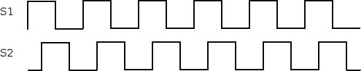
Sample encoder wheel: 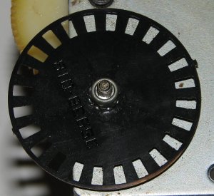
Sample optical switches (sometimes also called opto interrupter/opto coupler/etc): 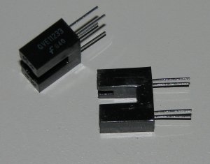
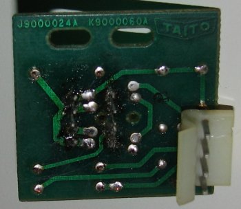
Sample schematic and explanationThe circuitry needed to generate the output described above is actually very simple. A sample circuit (from Arkanoid) is shown below: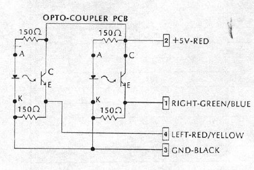 One can clearly see in the schematic that the left and right portions of the circuit are identical, so consider just one side of the schematic: 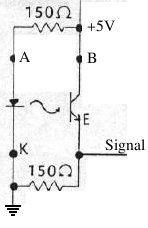 Now, looking at this simple circuit, one can see two distinct parts: on the left is a simple LED circuit, resulting in the (IR) LED always on. On the right side is the receiver. When the (IR) light from the LED shines on the receiver, the transistor is "on", meaning the signal line is high. When the LED output is blocked, the transistor "turns off", meaning the signal level goes low. 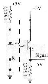 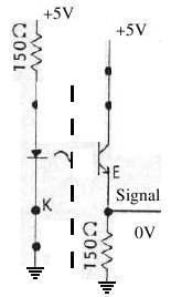 PracticalArkanoid Optic Encoder BoardThe Arkanoid spinner optic board I'm familiar with is marked "J9000024A" and "K9000060A" and has the Taito logo on it. It matches the schematic above.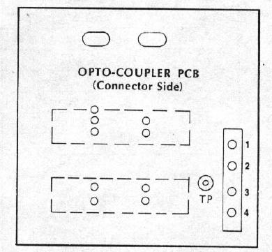
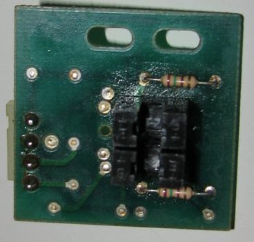
Repairing/Replacement PartsThe original Arkanoid encoder board is very simple and uses just resistors and optical-interrupters (optical switch -- which contain an IR LED and IR receiver). The only components likely to fail are the optical switches, when the IR LED dies. The optical switch used was a Sharp IS04, which is no longer easily available. Possible replacements are (note pinouts are not all the same, so some may take some adapting):
Expected VoltagesWhen debugging the Arkanoid optic board, it's best to start with just Gnd/+5V (pins 2 & 3) connected. The expected voltages are:- IR LED unblocked
- IR LED blocked
The next step is to connect the left/right wires (pins 1/4) and check again. You'll likely see the output voltages drop some from the out-of-circuit measurements, but if you see a substantial drop from 5 (say 2-3V instead of 5), you probably have a weak opto-switch. My spinner only goes one directionThis is probably due to one weak opto-switch on your optic board. With the optic board connected to the game, you'll probably see one of the outputs doesn't drive a very strong signal (maybe 2-3V). You can try switching the left/right signals (pins 1/4). If the spinner no longer works at all, it is one bad opto-switch on the board. Either replace your optos (may as well do both while you're at it), or replace the optic board.The reason for this is how most games decode the optic board signals. Typically, a couple D flip-flops are used and the signals are used as clk and direction. If the signal used for clk is strong enough (but not dir), a valid movement is generated, but always in one direction. If clk is too weak, then no movement is generated. My spinner doesn't move at allThis could be any number of things -- bad optic board, bad logic board, etc. One easy test to try first is to swap the two outputs from the optic board (pins 1/4). If you now get movement from the spinner, but only in one direction, you have one bad opto-switch on the optic board. Either replace your optos or the whole optic board. If swapping signals made no difference, verify the voltages on the optic board are as expected. If the output signals look weak, you probably need to replace the optos on the board.Otherwise, try a different logic board to see if the problem resides on the game board. Atari Optic Encoder Board (Tempest/Championshop Sprint/Tempest/Football/Missle Command/etc)I have not actually worked with one of these, but someone sent me some pictures (thanks Malcolm). Once again, this works the same as every other optic board I've seen (surprise, surprise).NOTE: it appears to me that +5/GND are switched from the Arkanoid/Michael Grugel board. Be sure to check that before hooking it up (not that you'll damage it, but it won't work). 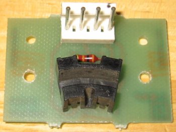 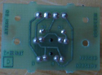 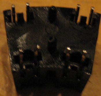 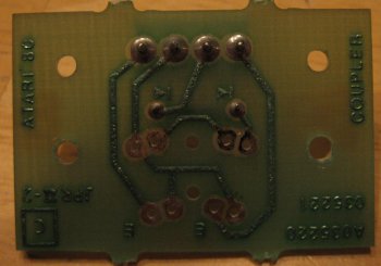
Notice that this board mounts the opto switches at a strange angle. This is because of how Atari made their encoder wheels (I'll post a picture eventually). If you need to replace one of these boards, you might want to just buy a new non-Atari encoder wheel and use a more standard (and therefore easily/inexpensively attained) optic board. Also note that the opto switches actually come as 1 big package that contains 2 switches. Inside the plastic shroud is the same as usual opto-interrupters. I don't have the measurement of pin spacing. If you do, feel free to share. The pinout (ignoring spacing) looks the same as H22A1, so 2 of those may be a good replacement. If they don't fit, you could open up the H22A1 and use the two components (IR LED/Receiver) in the original shroud. Note: This same optic board (or very similar) is used in (at least some) Atari trackballs. The 4" trackballs (Football/Missle Command/etc) definitely used these. Quarter Arcade sells replacements. Sources for replacement boardsI have tried the boards from Michael Grugel and the Taito originals (and my own home-built copies). Michael's are essentially reproductions of the Arkanoid board. I have been very pleased with the quality and price of the boards. They are also suitable for trackballs, but I haven't tried them in that application (yet).Any of these boards _should_ work with most spinners/trackballs/optical steering wheels. The only considerations are mounting and pinout.
Sega Optic Encoder Board (Turbo/??)Another one I haven't worked on, but have seen pictures of. This is actually a somewhat unique design in that the outputs are actually driven using a discrete transistor beyond the opto in the opto-interrupter. This should make them less susceptible to marginal signals from the opto. I'm not sure if it was the original part or not, but a NEC PS4001 was found on an old board. Fairchild H22A1 should be a drop-in replacement.This board is fairly different from most other optic boards in that it has built-in contacts on the board and is to slide into a connector as a jamma board does. I'm not aware of any repro boards, so the best bet on these is probably repair. Picture coming soon? TronA modern equivalent for the original opto switch is OPB822SDKickmanOriginal opto-interrupter is TIL143. A modern (overpriced) replacement is NTE3100. Another option is TCST2000, but seems to be hard to find. It also looks as if the QVE00118 from Fairchild would work fine. Anyone care to test? Please email me with results if you do.Interfacing with a PCOptical arcade controls such as trackballs, spinners and optical steering wheels (ie Pole Position, Super Sprint, etc) can easily be interfaced to a PC via PS2, USB and serial.OptiPacThe easiest way to achieve this is to use an OptiPac board from Ultimarc. The signal outputs from the optic boards connect to the OptiPac and that connects to the PC via USB or serial. This is the method I'd recommend as it's the cleanest and easiest. Ultimarc has a great lineup of high-quality products and excellent support.Hacks (or, I'm too cheap to buy an OptiPac)If you are too cheap to buy the OptiPac (it's really pretty inexpensive) or just get satisfaction from building something yourself, you can try converting a computer mouse to a optic board signal to PS2/USB/Serial converter. The interesting portion of the mouse controller is the single IC they all have. These ASICs serve the same purpose as an Optipac. Unfortunately, they are not easily available in hobbyist portions and/or not well documented. The easiest and cheapest way to get these chips is to cannabilize a mouse. However, this means some work determining what is going on for each board since there are many variants of the controllers (and some are simply small microcontrollers). Like their arcade cousins, these boards also use IR LEDs and IR-receivers as optical switches. They also use encoder wheels, though normally quite a bit smaller than the arcade versions. They have also squeezed as much cost out of them as possible, meaning that things have usually been somewhat simplified to save parts cost. Normally there is just 1 IR LED per axis, shared between the 2 receivers for the axis. The receivers have been combined into 1 3-pin device that actually contains 2 IR receivers. In addition, many mice play tricks with driving the LEDs. Some actually pulse the LEDs at a high rate in order to save power, extend the life of the LEDs, and increase LED output. When the LEDs are being pulsed, they can be driven harder in order to generate a brighter light. Another thing that will be found inside some mice (Logitech is one) is some non-standard parts which I still don't fully understand. These contain a 3-pin IR LED and some contain a 4-pin receiver. When time permits, I will investigate. If someone else already has, please consider sharing what you know.Another way to tackle this problem would be to write a simple program for a small microcontroller. However, this is probably not cost effective since you can usually find old mice for less than $5. In addition, hacking the mouse provides a nice cord/connector. As the old ball mice supply dries up, the microcontroller route may be the way to go. This will require implementing the PC communications side of things (probably USB) as well as the optical signal decoding. Working: Microsoft Intellimouse v1.1A (p/n 97599)
More info/pics coming. Working: Microsoft Intellimouse v1.2A (p/n X04-72167)
More info/pics coming. In Process: Microsoft Intellimouse v2.1A (p/n 63607)
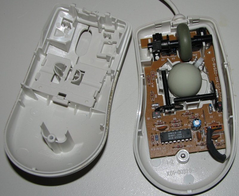
Internally, this model is marked with board 900-336-126 Rev C. An interesting difference with this one is the IR LED/receivers are covered with a black plastic shroud. Apparently there was enough light-leakage into the case (probably between the buttons) that these shrouds were required. Other models have the sensors toward the back of the mouse, so this apparently isn't a problem. I have also seen a mouse marked Microsoft for Toshiba (p/n 92608), also marked 2.1A, which looks to be identical to the Microsoft p/n 63607 (not surprisingly). Working: Genica Scrolling Mouse (model GN-115)
Ok, this one turned out to be as easy and straight-forward as it appeared. There are no tricks here -- just a simple, documented design. In this case, I actually left the IR LED and only removed the IR receiver(s). The center pin of the IR receiver is +5V, as usual. The 2 other pins are the 2 signal outputs. I connected these 2 pins to an Arkanoid encoder board (pins 1/4) and borrowed +5V/Gnd from the connector (nicely labeled on the board) and routed those to pins 2/3 of the Arkanoid optic board. Bingo -- in business. This is a great mouse to use if PS/2 fits your needs, since it is simple and the datasheet is available. In fact, I plan to de-solder the IC itself and mount this on my own custom encoder board. One warning: be careful -- this is cheap both in price and quality and therefore fairly delicate. Both the connector and the gauge of wire used is pretty light. The mouse: 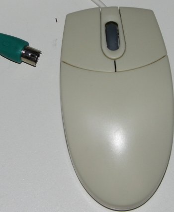 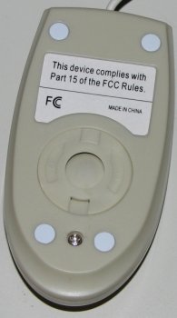
Inside: 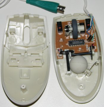
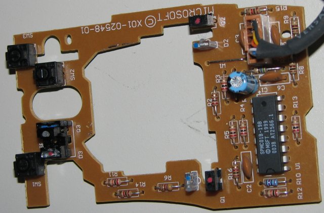
The board: 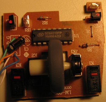 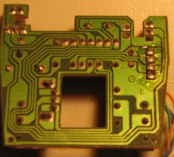
The mod: 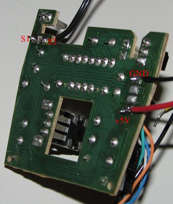
For the modification, I did just one axis (X). I removed the 3-pin IR receiver (and left the IR LED). The center hole can be left unused or used for +5V. The two outer holes take the signals from the opto-interrupters (or signal pins 1/4 from an Arkanoid optic board). +5V/Gnd can be found various places on the board. I just used the input header pins. Connected to the optic board: 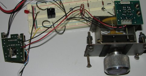
This shows the spinner connected to the mouse and working great. The +5V line from the mouse goes to pin 2 on the optic board, GND goes to pin 3, and the 2 signal lines from the optic board go to the IR receiver outer pins on the mouse board. Ignore the breadboard. I was only using it to easily connect the wires from each board for testing. Working: Unknown Brand 2-button USB mouse (model MS-009S/-BLK)
This one was fairly interesting. Due to the epoxy blob, it's impossible to see what goes where, but I did scope it. When plugged into a USB hub, I saw +5v but no action - IR LEDs not lit. After connecting a computer to the hub as well, things came to life. The LEDs were being pulsed (at a rate I didn't bother measuring). None-the-less, I decided to press on and see if the modulation was expected on the signal lines. Thankfully, the answer was no. This was a simple as removing the IR receiver, using the center pin for +5V and routing the other 2 pins to the output of my new IR receivers. I stole gnd from elsewhere on the board. I used the +5 to power the emmitter side of the opto switches (through a resistor). That was it -- works great. So, if you want USB, this is probably a great choice. Simple, small and CHEAP. Enjoy. The mouse: 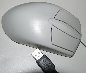 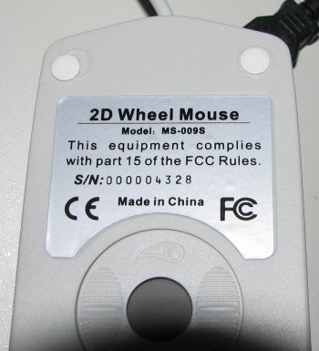
Inside: 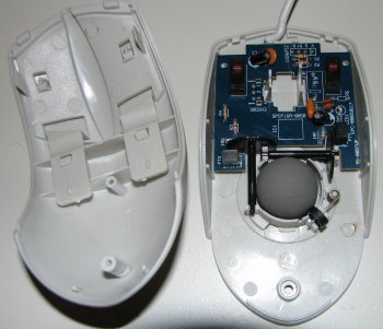
The board: 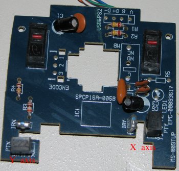 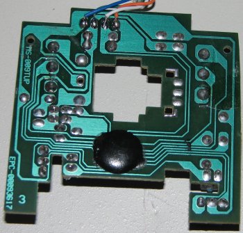
LED Drive Signal: 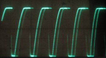
The mod: 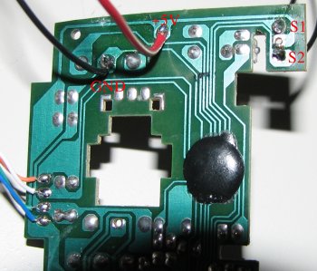
For the modification, I removed the 3-pin IR receiver for the X-axis (repeat for the Y-axis if you need the input). The middle pin can be left unused or used as the +5V source. The two outer pins are the two signals from the opto-switches. Ground and +5V were pulled from elsewhere on the board. The spinner: 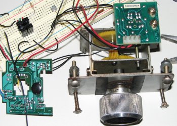
Here you can see the whole hookup. In this case, I used the Arkanoid optic board rather than building my own like I normally do. S1/S2 go to pins 1 and 4 on the optic board. +5V goes to pin 2 and GND goes to pin 3. Ignore the breadboard -- in this case I'm just using it to route the wires from the mouse board to optic board. SEE ALSO: Connecting a trackball via a hacked ms009s-blk mouse. Other successful conversionsAnyone else have success? Anyone brave enough to tackle a Logitech mouse yet? It's probably next on my list... I've been told these modulate the signal going to the IR LEDs (like the v1.2A MS mouse), but also expect to see that signal received. That probably means we'll have to drive the new IR LEDs on our optic board with the same signal -- probably using a transistor in order to provide enough power, since we are driving 2 LEDs per axis rather than 1 like the mouse uses. In theory, it sounds simple... :)Data SheetsZ86317 - Intellimouse v1.1A and 2.1ASC84510 - Genica GN-115 SPMC01B-198 - Anyone, anyone? (Intellimouse v1.2A) Useful linksUltimarc: OptiPac - This is really the way to go for interfacing arcade spinners, trackballs, and optical steering wheels to a PC. Much easier and cleaner than the mouse hack. |